Make sure you’ve read the Ultimate DAF System Buyer’s Guide Parts 1 & 2 before starting here.
Part 1 of the Ultimate DAF System Buyer’s Guide
Part 2 of the Ultimate DAF System Buyer’s Guide
5. Dissolved Air Distribution Methodology
The method used to distribute whitewater into the incoming wastewater stream makes all the difference in the way sludge forms and floats inside the DAF vessel. Let’s examine two different approaches.

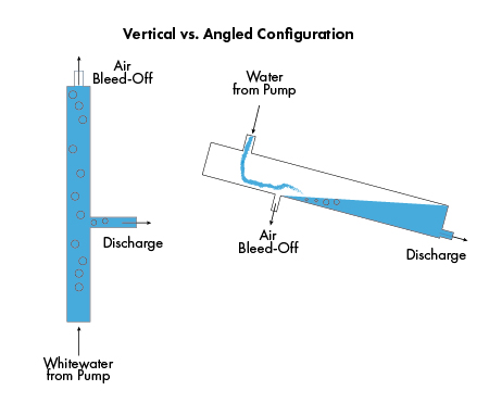
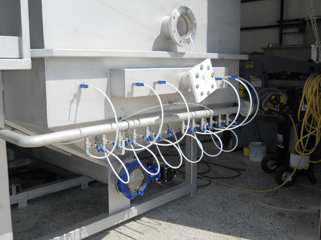
Some DAF manufacturers employ a specialty whitewater pump, vertical saturation pipe and diaphragm valve assembly to generate and inject whitewater into the incoming wastewater. Others use ANSI recycle pumps, an angled air saturation tube, and a whitewater distribution manifold with multiple ball valve and tubing assemblies. A comparison of these two configurations might sound like splitting hairs, but it’s definitely worth some consideration.
- The vertical saturation pipe configuration is designed to bleed off air that doesn’t dissolve into solution. While most excess air will escape from the top of the tube, the side-mounted whitewater discharge line will draw some portion of it into the tank. As excess air enters the flotation cell, large bubbles form and burp at the water’s surface. These bubbles disturb already floating sludge and immerse solids back into the water.With an angled configuration, excess air escapes out the elevated portion of the tube as whitewater flows out from the lowest point. No undissolved air can enter the flotation tank because the water flows from top to bottom, not the other way around.
- DAF systems that use vertical tubes typically only have one dissolved air injection port. When flowing 100 gpm (1.67 gallons per second) of wastewater into the flotation cell, a single dissolved air injection point is unable to effectively and evenly spread whitewater over the entire incoming solution. Some portion of the flow gets a huge shot of whitewater, while other parts go entirely without. It’s up to the hydraulic patterns inside the flotation cell to distribute the bubbles. Often times this works, but it’s unpredictable and uncontrollable. A habitual problem with this design is that solids cannot float to the water’s surface quickly enough to keep up with the incoming flow. By all calculations, a system designed to process 100 gpm of wastewater is unable to achieve that flow rate because solids are not separating quickly enough. DAF systems with whitewater distribution manifolds do not have this issue. Numerous whitewater injection ports are placed across the width of the flotation cell at different heights to evenly distribute micro-bubbles all throughout the DAF tank in a controllable manner.
- The start-up routines for these two configurations also varies by nature of the whitewater injection system. A single air injection port saturates the tank with whitewater from one origin. As tanks are sized longer and wider, it takes more and more time for the bubbles to disperse throughout the whole tank. Some manufacturers’s DAF operation manuals suggest allowing 5-10 minutes for tank saturation before opening the wastewater influent valve and proceeding with treatment. DAF systems with an air distribution manifold are fully saturated within 60 seconds or less. Shorter start-up time means less waiting around and more getting work done.

The lesson is is to get in closer and examine the design differences. The details matter. Ask the manufacturer about their design justifications.
6. Application Specific Design
Think of a hammer, a tool meant to deliver impact to an object. Now, picture one in your mind. What do you see?
If you’ve ever worked in carpentry maybe you visualized a claw hammer. Metalworking? A ball-peen hammer with a hemispherical head. Maybe you’re a stonemason and thought of a brick hammer with it’s long chisel-shaped blade. Everyone thinks of the hammer they use in their trade. But, no one should know better than the hammer-maker which one is the most appropriate for a specific task.
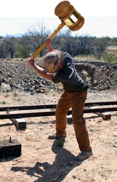
A DAF system manufacturer should have that same level of expertise and knowledge about which DAF system design is most suited to a specific application. If a designer is using the same DAF system for a dairy acidulation process as they use in a cattle abattoir plant, that’s like a rail worker using a judge’s gavel to pound in a railroad spike – similar tool, wrong application.

The application specific design largely comes down to materials selection and process engineering. Take for example a DAF system used in a cattle kill plant. Without understanding that these types of facilities generate wastewater laden with sandy, gritty materials, a manufacturer may opt to use their design standard, say a cast iron pump. Unfortunately for the person who buys this DAF system, their gritty wastewater will wear pin holes in the pump casing and eventually cause a pump failure. This results in down-time and replacement of the most expensive component on the system. When something like this happens, not only does it reflect poorly on the manufacturer, but also on the engineer/consultant that presented it to the end client as the right solution. The master craftsman would understand the gritty nature of cattle wastewater and select a pump casing with high Brinell Hardness, like CD4MCu.
On the process side, the DAF designer should understand how to properly calculate and interpret hydraulic surface loading rate, solids loading rate, and air-to-solids ratio based on the application at hand. Solids in poultry kill plant wastewater separate infinitely easier than those from the effluent of an activated sludge system. Using the same values for each of these processes would likely result in an oversized poultry DAF and an undersized bio-mass separator.
You’re the one buying the system, don’t be afraid to question why a specific configuration was selected over another and be sure to ask for an explanation of the calculations behind your system sizing.
Continue to the Conclusion of the Ultimate DAF System Buyer’s Guide

